Trending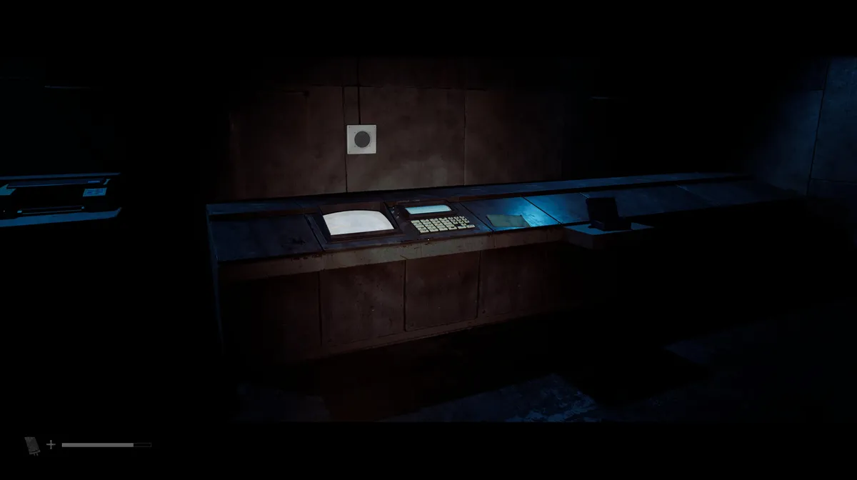
By the time you reach this room in Silent Hill: Townfall, developed by No Code and published by Konami, you’ve already fought, sneaked and puzzled your way deep into CEG headquarters. The generator’s running, you’ve got the keycard for this console room, and the door has shut behind you. What’s waiting inside is arguably the longest, fiddliest puzzle in the entire game, so settle in. This walkthrough covers the “Different” route through CEG HQ, matching the codes and combinations found on this particular run. If a number here doesn’t match what’s printed on your own Remote Systems Control document, trust what’s in front of you over what’s on this page, since a few of the IDs appear to shuffle between playthroughs.
What the room is asking you to do
Open your inventory and check the objective at the top of the screen. It reads “Relive the events on CCTV”, which is exactly what it sounds like: you’re about to replicate, step by step, everything the two shift operators on duty that night did before things went wrong.
Take a moment to read the room itself before touching anything. There are two consoles. The one overlooking the huge clamped chest tells you there’s a valve issue and won’t let you interact with it yet, so leave it alone for now. The console you want has a keypad covered in unlabelled symbols, the Remote Systems Control document pinned up on the right, six CCTV camera feeds numbered 000 to 006 down the left, and a small printer above the keypad spitting out a log of everything the operators did that night.
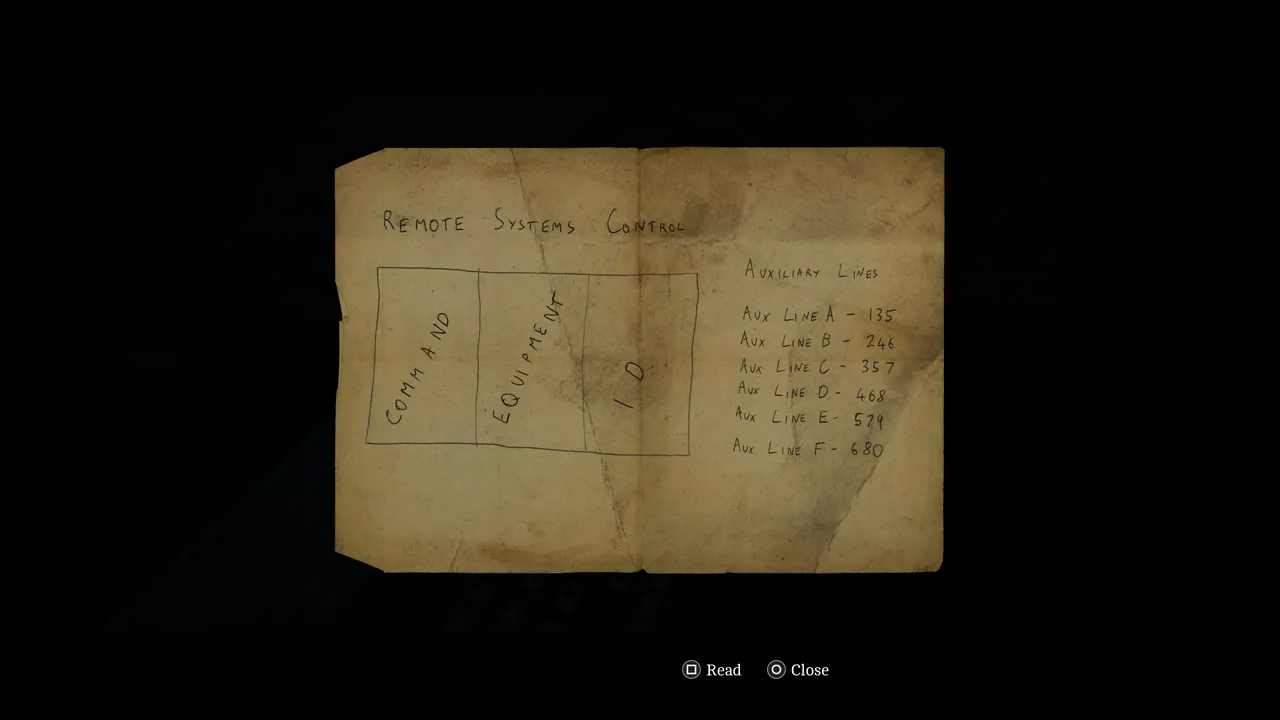
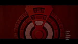
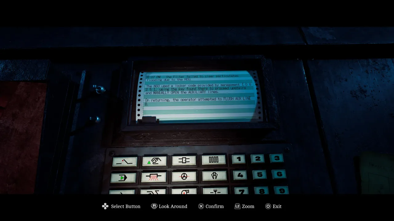
Everything printed in capital letters on that log is your next instruction. The Remote Systems Control document explains how to act on it: it lists three columns, Command, Equipment and I.D., which map directly onto the keypad. The first two columns of icons are commands, the middle two are equipment, and the number pad handles the ID code. For this guide, positions are given as row and column, so row 1, column 1 means the top-left icon, and each combo also names the icon itself so you can spot it without counting squares.
Step 1: Open Valve B
The first log entry reads OPEN VALVE - B -. Check camera feed 005, and you’ll find the tank for Valve B, stencilled with the code 254.
Enter row 1, column 1 (a jagged zigzag line with a small red arrow at the tip), then row 2, column 3 (a circle with a dashed diagonal line through it, like a dial or valve symbol), then 254, and confirm. That should print the next log entry.
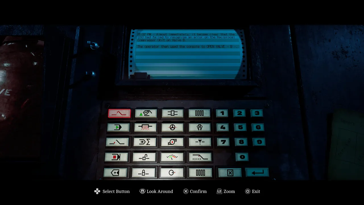
Step 2: Start Filter A
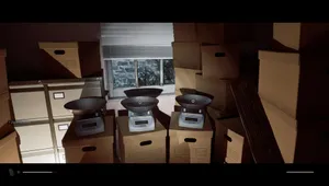
The next instruction is START FILTER - A -. Switch to camera 000 for a look at the Filter Unit room, where the code 103 is marked on a crate.
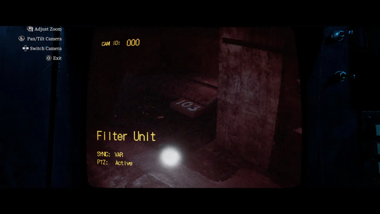
The combo here is row 2, column 1 (a solid green arrow pointing right), row 3, column 4 (a small funnel-shaped icon with dashes underneath it), then 103.
Step 3: Manually open the Auxiliary Lines
The next log entry is a bigger one, and it comes in two parts. The first half tells you to MANUALLY OPEN the AUXILIARY Lines, and this time the game hands you a combination rather than a camera clue: 0825. Back out of the console and look for the locker that’s now accessible in the room. Dial in 0825, and you’ll find the AUX Key inside.
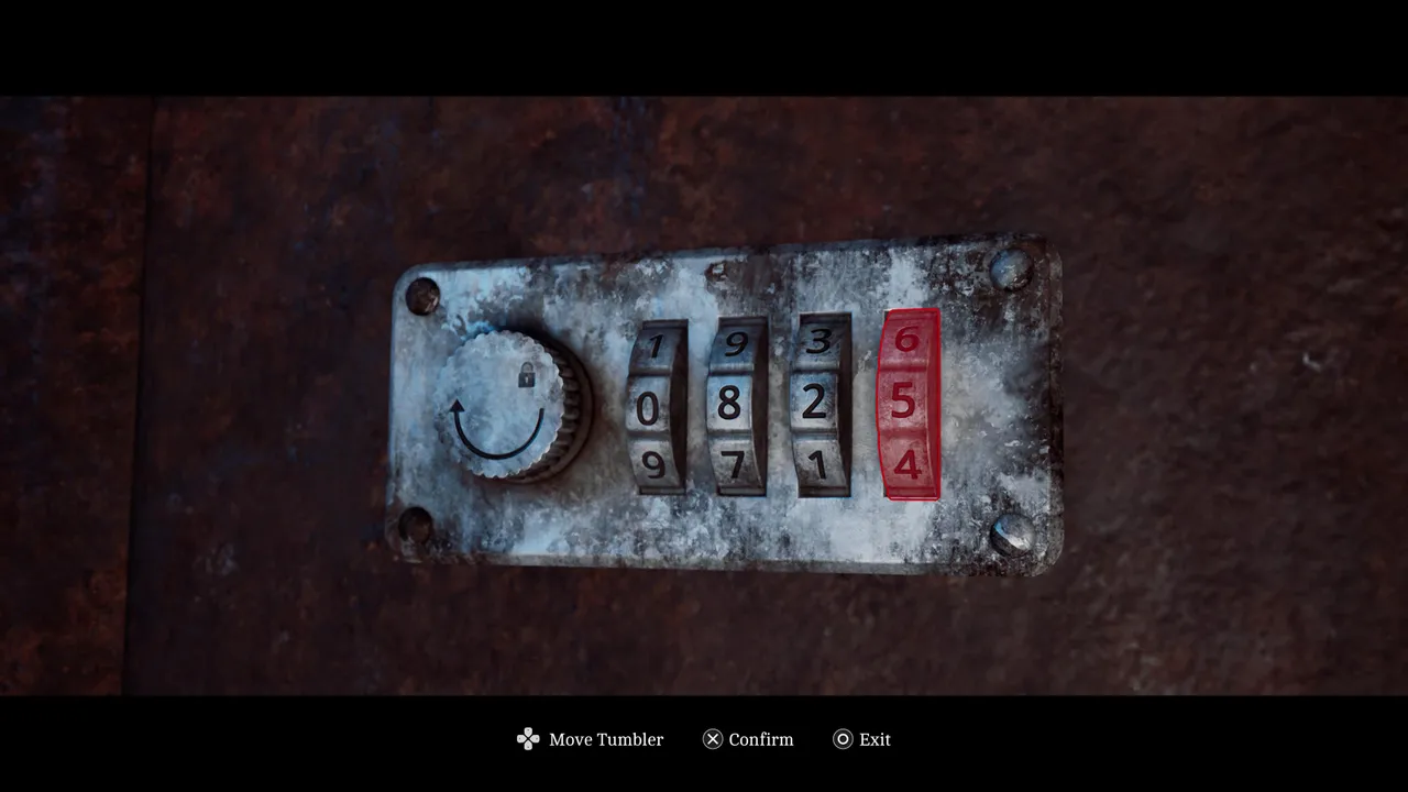
That key opens the AUX room, but getting there means heading downstairs, where Weight is stalking the area, so keep your distance. Reach the lift and ride it to the first floor, where you’ll run into more enemies depending on your difficulty setting, before you can unlock the AUX room.
Step 4: Solve the pipe puzzle in the AUX room
Once you’re inside, search the nearby locker for a floppy disc, slot it into the disc reader beside the computer, and boot the machine up. The file on the disc is your clue for the room.
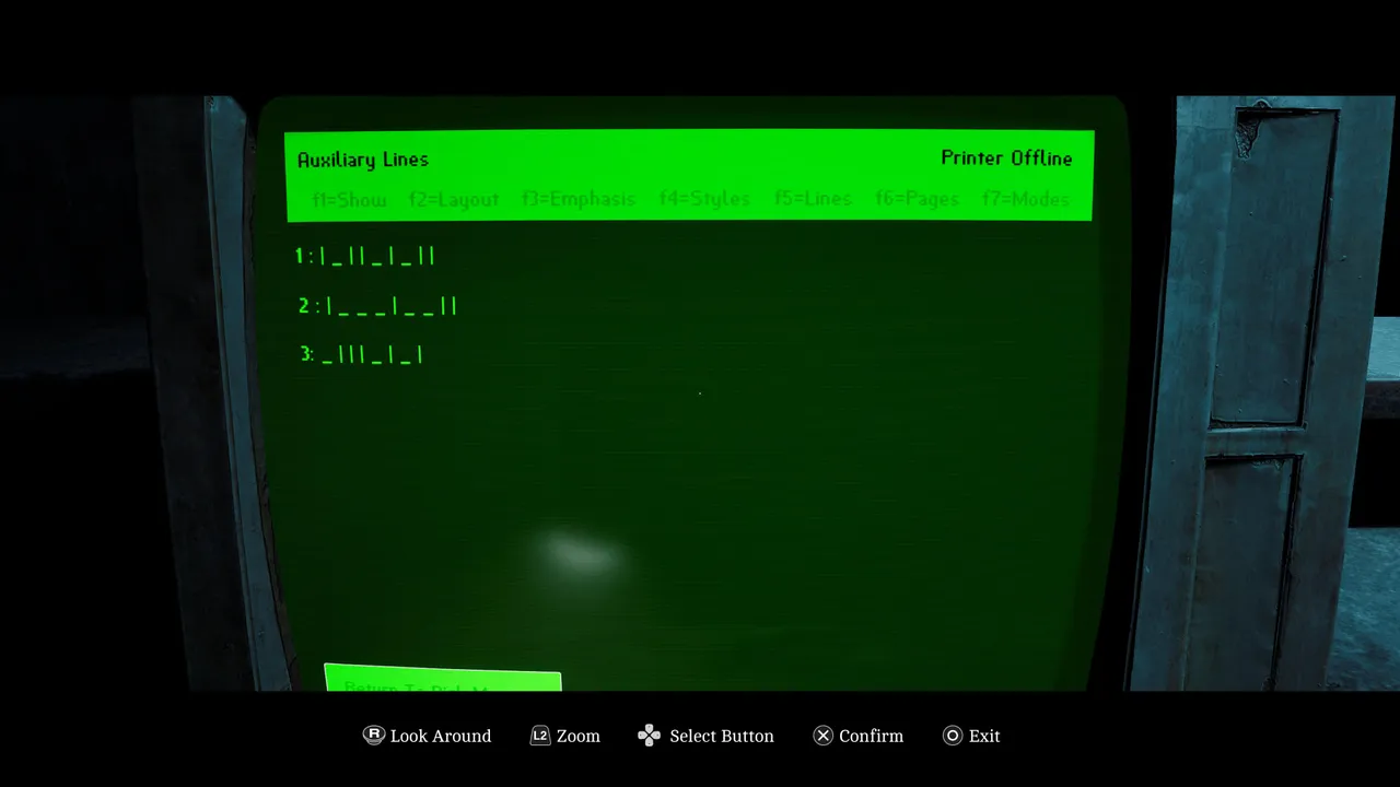
You’ll see three physical pipelines running through the room, each carrying a cluster of valves, and each matching one of three symbol strings on the file, numbered 1 to 3. Tell them apart by the white stripes running along them: the pipeline with a single stripe closest to the floor is line 1, the one in the middle is line 2, and the one closest to the ceiling is line 3. The arrows painted next to each pipeline show which end to start setting valves from, and the vertical and horizontal marks in the file correspond to each valve’s correct position along that line.
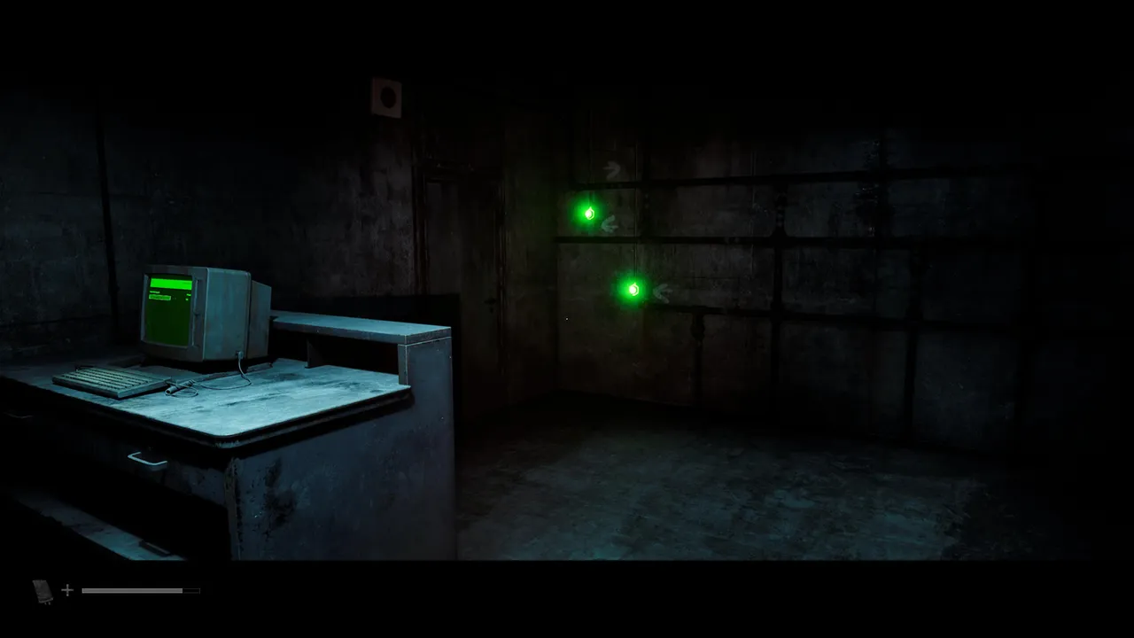
The easiest approach is to solve lines 1 and 3 first, then tackle 2. A correctly set pipeline glows green, and a wrong turn glows red, so working the two easier lines first helps you spot, by elimination, which valve belongs where if you’re ever unsure. If you’re stuck telling line 2 and line 3 apart on a shared valve, check the file again: horizontal marks are always accompanied by a small stripe, so that detail settles the tie.
With all three lines showing green, head back to the control room. Weight is still down there, so watch your step on the way.
Step 5: Flush Aux Line B
Back at the console, this closes out the second half of that earlier log entry: FLUSH AUX LINE - B -.
The combo is row 2, column 2 (an icon that looks like a spray of mist or water droplets), row 4, column 4 (a thin diagonal line dotted with small dots), and the code straight off the Remote Systems Control document: 246, which is Aux Line B’s listed ID.
Step 6: Stop the Regulator
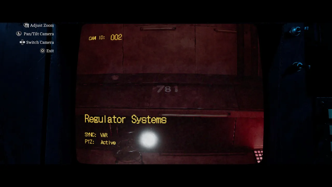
The next log reads STOP the REGULATOR. Camera 002 shows the Regulator Systems room and the code 781.
Enter row 4, column 1 (a rectangle with a solid red square inside it), row 4, column 3 (a gauge-style icon with a needle running along a red-to-green scale), then 781.
Step 7: Unlock the door to Valve F
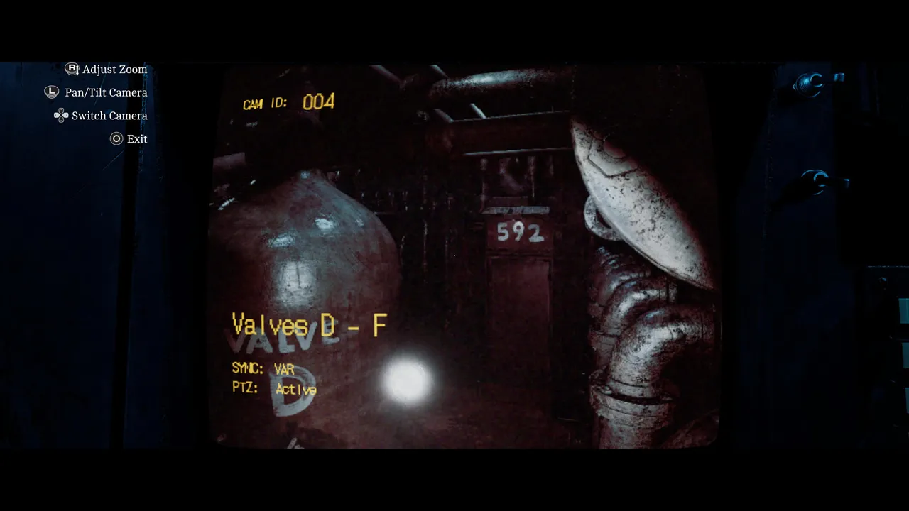
Next up: UNLOCK the DOOR leading to VALVE F. Camera 004 gives you the code, 592.
The combo is row 4, column 2 (an open padlock icon), row 1, column 3 (two vertical bars joined by a short crossbar, like a pipe fitting), then 592.
Step 8: Manually open Valve F
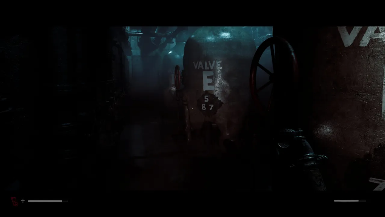
This one doesn’t take a keypad combo either. The log tells you to MANUALLY OPEN VALVE F, which means another trip downstairs, this time one floor further down than the AUX room, to the door you just unlocked (check your map if you’re unsure exactly where that is). Expect resistance on the way.
Turning Valve F by hand sets off a chain reaction, and Weight comes down after you as the floor fills with more enemies. This isn’t the moment to clean house; get the valve turned and get yourself back to the control room in one piece.
Step 9: Release the clamps
Back in the control room, the final log entry points you to the CLAMP RELEASE MODULE, which is the other console, the one that shut you out earlier over a valve issue. Before touching it, grab the user manual sitting by the printer nearby. It walks you through the whole procedure in order, and it’s far easier to follow than guessing.
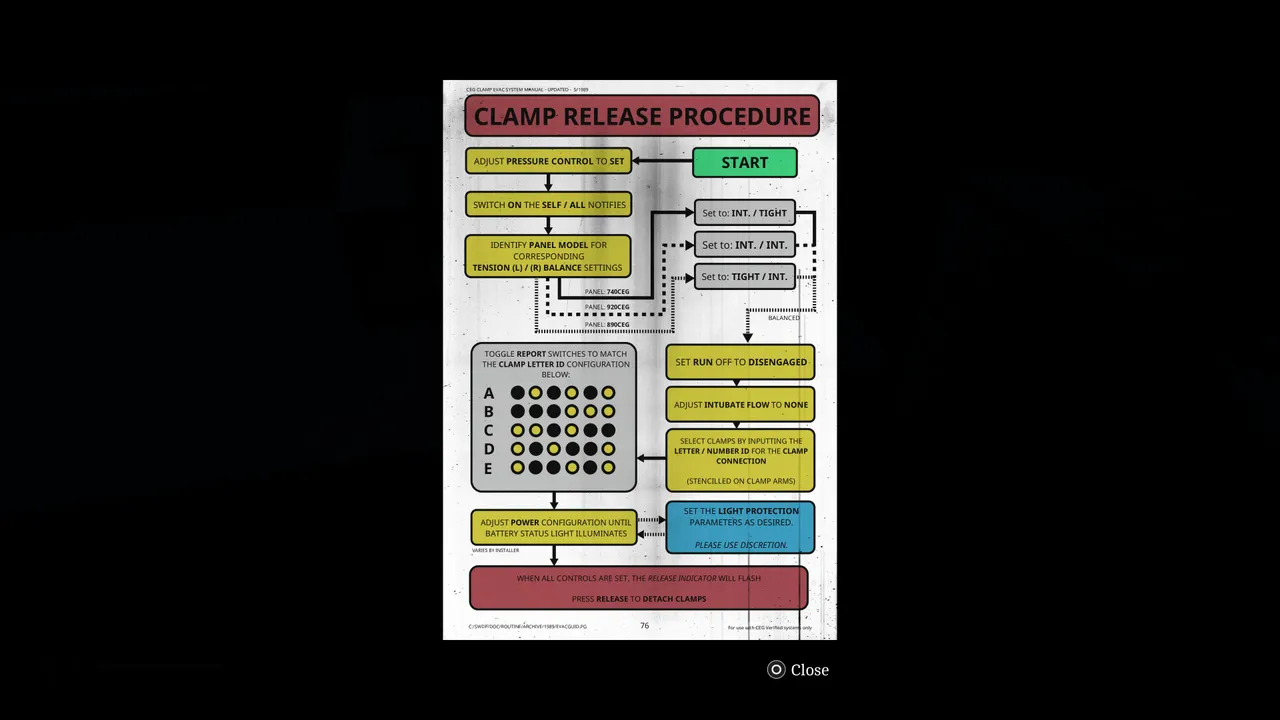
The one variable is the Panel Model, printed in the upper-left corner of the console itself, which decides your Tension (L) and (R) balance settings. Match your model to the manual’s flowchart, then toggle the Report switches to mirror the Clamp Letter ID grid shown for that model: yellow means the switch is on, and black means off. Work through the rest of the manual in order: pressure control, the notify switches, run off, intubate flow, the clamp connection ID and the power configuration, and set light protection however you like (the manual’s own advice is “please use discretion”, which is about as close to a joke as a 1989 evacuation guide gets).
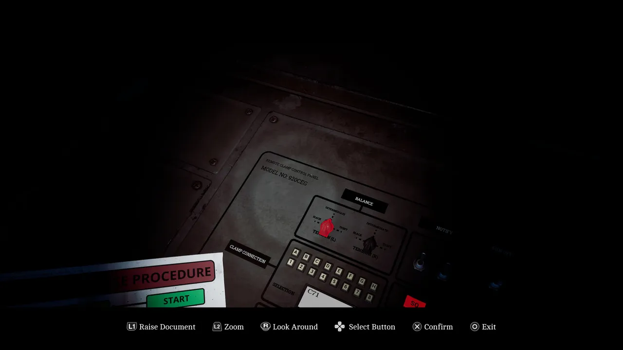
Once every setting lines up, the Release Indicator starts flashing green. Press it, head downstairs (Weight’s cleared off for good by this point), and turn the wheel in the middle of the room. That’s the puzzle done.
Quick tip
Keep half an eye on the Remote Systems Control document throughout rather than just at the start. Several of the equipment icons look nearly identical at a glance, and there’s no penalty for double-checking before you commit to a combo, only for guessing wrong and having to start the entry over.
DON'T MISS!